Hi all,
I guess my last post was rather brutal, just pictures and no words, but sometimes a picture tells a thousand words. Yes it is true that my VR narrow gauge layout is no more.
This decision has been kept in the background for nearly a year now and you wouldn't need to be a good detective to see that the posts were getting further and further apart. Many thoughts re the layout were had prior to making the big decision.
The true reason is a family one and I have explained this reasoning to anyone I feel I am close to. When you get to make this choice there are other factors that all come together that have to be sorted out. Sometimes we live in a cocoon and don't think and look at all aspects. One of the reasons listed in my brain is that VR narrow gauge is a specialised prototype that is not common, so will it be harder to get rid of? Well the answer to that question is that within about two weeks of advertising I reckon around 90% of my models have been onsold.
The selling of the models went great and I think the rarity of the product combined with the expert assembling, painting and weathering by two modellers - Stephen Postma and James Black of all the rolling stock made this easy. Ian Storrie the principal behind Ian Lindsay models has retired a few years ago so there will be no more of the excellent kits from him. This made his kits more valuable and sourced. So to haul all these kits that were turned into beautiful models, the linchpin was the Haskell model of the On30 NA.
And so for two weeks things were really busy sorting out emails, messages. packaging and posting items as the room started to shrink of things. But the key factor to moving the other layout there was the sale of the 'portable' sectionalised parts of the layout. Something I realised when I started the narrow gauge was to make the baseboards removable so under any type of circumstances that may arise in future, it can be easily disposed of. So amongst the listings of all 'items' for sale I included on the last page details and more importantly the sizes of the layout for sale.

 |
| GOING |
 |
| GOING |
 |
| GONE |
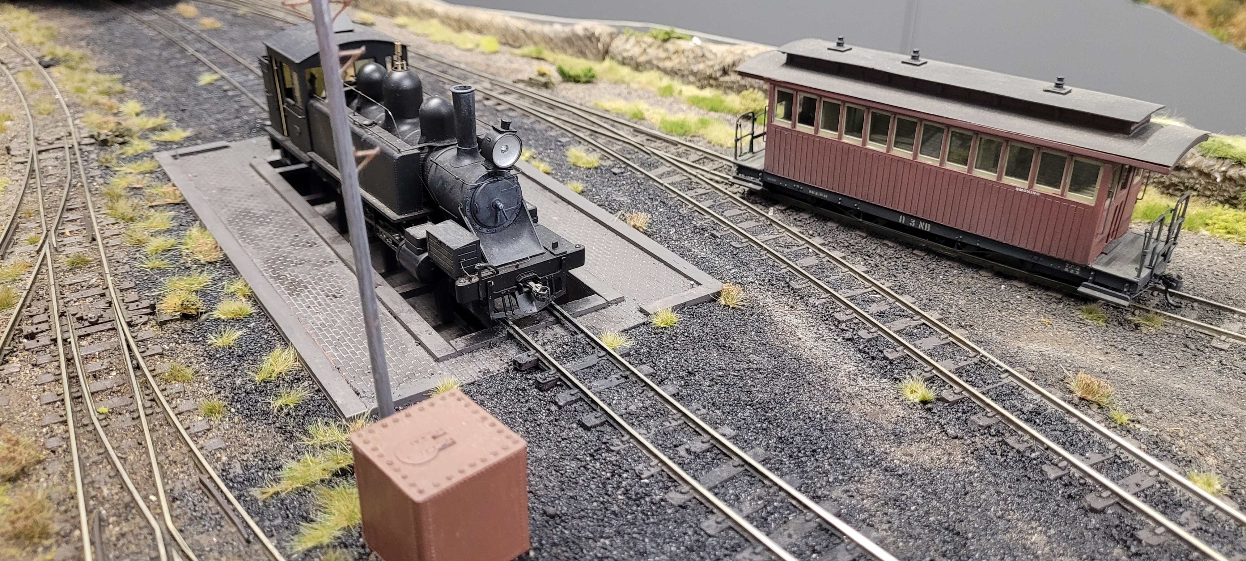
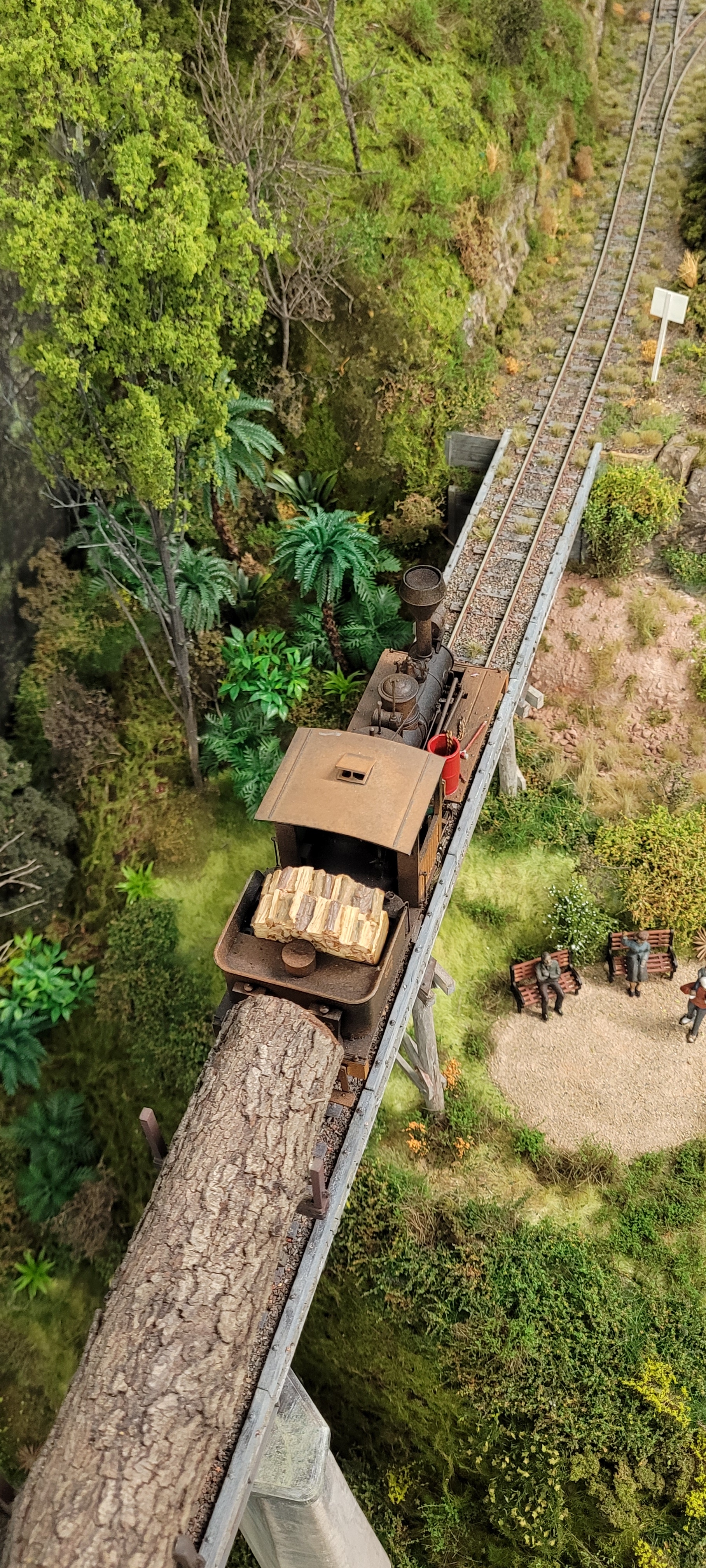
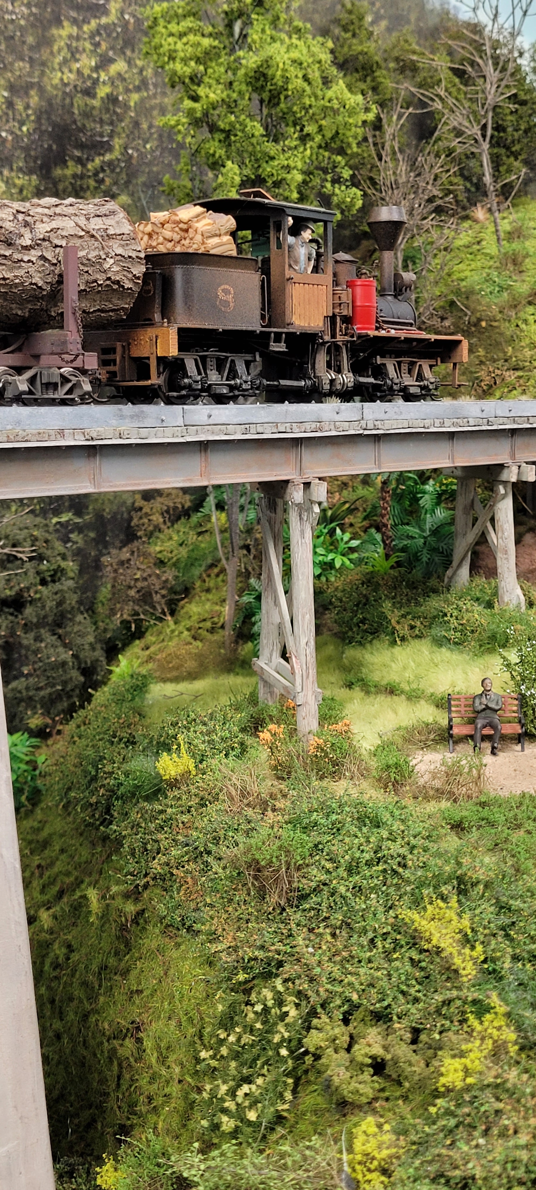
In the gone photo above it can be seen where all the portable sections were located. The layout started at the terminus at Eden and was then progressively modelled on towards Bega. Two large bridges were built along the way, the first being a trestle bridge loosely based on the Monbulk trestle on Puffing Billy railway. This one was fully completed before moving onto Broadwater to model.When it was time to build the Thomson River bridge, I realised this was going to be a major build and take some time. So to enable some sort of operation before its completion a diversion was made for the track towards the back of the baseboard. This allowed trains to run and the front was clear to commence construction of the bridge. It ended up being around three years from go to operation over the bridge. There was some consideration of donating the bridge to a heritage group but as my son wanted it retained it will remain and hopefully be worked into the HO railway. It may look odd with HO trains but at least it will hang around a bit longer.
 |
ALL PACKED UP AND READY TO GO
|
Although it may have been a hard decision to abandon SCR there were these points to consider:
- The stimulus of a new venture going from HO to On30
- All the research required. It becomes a new world where you have to learn the how, when and why of the new era to be modelled. I have chased up every plan, book information, photos etc that I could which helped get that true narrow gauge flavour into my modelling. I did the same for when I was modelling NSW in HO. I remember a line that the painter Kenneth G Bowen said to me when his wife said "No not another book" To which his reply was "Research, research, research" I stand by that.
- Part of the research is visiting the locations I am modelling. Our groups visits to Melbourne often use to incorporate day trips on Puffing Billy out to Gembrook and back. And also we did two trips on the SteamRail 'Snow Train' which incorporated a coach trip to Walhalla and a trip on the train out to Thomson. I used every minute of the stop at Thomson to snap as many photos of the bridge as possible and the guard kindly waited for me to get back to the train before departing for Walhalla.
- I started modelling narrow Gauge back in 2016 and I have made a lot of new friends along the way. The narrow gauge modellers have always been a friendly crowd and I hope to continue that friendship.
- Realising that O scale people are a way lot bigger than HO people, (and buildings etc)
Another consideration for abandoment was that I was waiting for an announcement for when and where the next Narrow Gauge Convention was going to be held. It was due for Easter 2025 somewhere and I was hoping for a NSW venue. But a final decision was to delay the convention until 2026 and my idea was to offer the layout as an open house layout visit, similar as to when I had the SCR open for the 2019 Convention at Erina. This delay in the convention sealed my decision to abandon SCR.
Over my 60 years plus of modelling I reckon I have tried them all including adding O scale recently in Narrow Gauge. All my decisions to make a layout change I must add have been painless with the thrill of a new venture overriding any sadness of just leaving the old one. Back in the mid to late 70's I decided to model some traction or tramways if you are in Australia. I left N scale to go HO traction, then went back to N scale etc, etc. The latest decision is to retry some HO traction modelling. Again it is all about the design, research, new friends and a challenge ahead as all the track and the overhead wiring has to be made. Yes call me crazy but thats what I seem to thrive on.
On the quite I have already made a start on collecting my traction models and if you want to see and follow if you are interested my new site is at South Coast Traction
And I have been helping my son build his layout in his bedroom. I have decided to move his layout into the space where SCR used to be and I will be up the other end working on South Coast Traction. Again if you want to follow the progress of his layout 'East Coast Rail' you will find it here East Coast Rail
Thanks to all that have followed South Coast Rail over the years and offered encouragement in your comments. I feel that the new arrangements will be the most suitable for all.
I also want to make special mention to the following for help on SCR where my abilities were non existent: Stephen Postma and James Black (Painting and assenbling models), Marcus Amman and Ben O'Malley (DCC installation), Roger Johnson (3D modelling of bridge piers), Nathan Wakim (laser cutting bridge girders) Russell Freeman (Milling of aluminium bridge girders), Ian Fainges (painting and weathering of bridge piers and also excellent figure painting) and sorry if I have left you out. As you can see there is a great team of people behind the final outcome of the layout, without their help, it would not have come out as well. What a great hobby!
Thank you all,
regards
Bob
 |
THERE SHE GOES, OFF TO A NEW HOME FAREWELL SOUTH COAST RAIL
|


