Wednesday, 12 February 2020

Phil'in in the day

2020 and our first 'train day' was due today. As per usual it always seems to rain on these days and today was no exception. We gathered over on the northern beaches of Sydney an area reknown for its famous rugby league team although kickoff is around another month away.
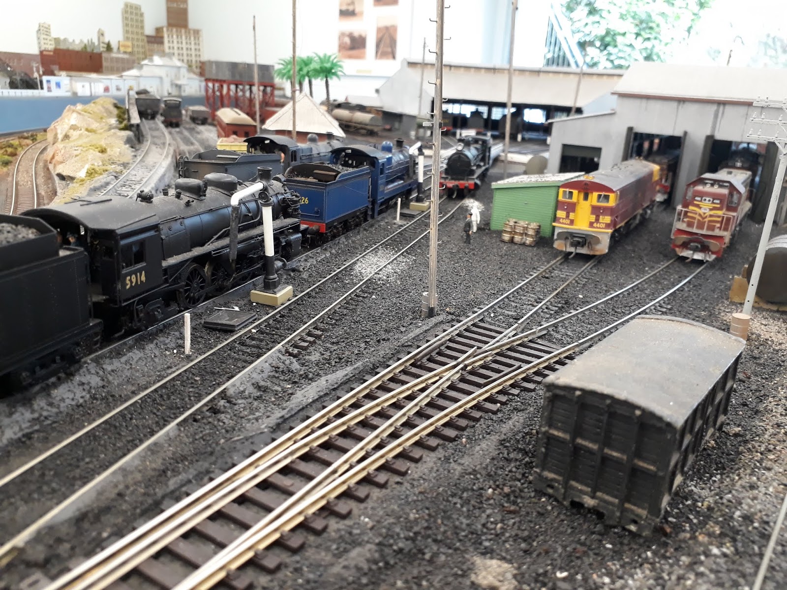
Phil has the ultimate train room situated under the house in a former garage that now exists in its final format. Beautifully presented with bright lighting, blue painted walls and finished off with some great photos of the northern line and well made finished off baseboards and complete with black curtain valance. What a man cave.
Various trains circled the layout representing trains of the bygone steam era. Coal trains are the four wheeled variety and BCH coal hoppers hauled by a sound 60 class garratt. No modern container trains found on this layout.
Since our last visit it seems only minor cosmetic changes and detailing has taken place. The amount of detail Phil has put into this layout is fantastic, each area has lots to take in. I particularly like his version of the Wickham Branch which in its day was full of various industrial sidings, a shunters delight. The branch on his layout also doubles up having storage/staging sidings built under.
So after spending some time absorbing the layout we ventured upstairs  for our barbeque lunch, some liquid refreshments, cake and coffee later and then off home in the afternoon traffic.
I'll let the pictures do the talking, another great day with some mates.

WICKHAM BRANCH


BROADFIELD LOCO

BROADFIELD


HONEYSUCKLE


BLUE SKY MINE

 
The End - Enjoy


Monday, 3 February 2020

Thomson River Bridge - 4

Don't know what happened to January but it is now February and time for my first post for 2020. 
As promised I have been continuing with work on the bridge, it is one of those projects that takes a fair bit of time and a lot of repetitious work with the various parts on the bridge structure. You have have to go head down and plough on. Part way through the project I was wondering two things - why did I pick this bridge to model and why did VR make it so long and big? But looking at my progress so far I am pleased that I have tackled this project. The finished bridge will be around 2 metres long this being done in O scale.
Before I decided to go ahead with the build there was a fair bit or research required. An almost essential requirement is a set of plans. An impossible task to go over the real bridge with a measuring tape to draw up plans and why build it if it was only going to be a 'close enough' build.
Through a forum I was able to get a set of plans for the bridge, even though they were unreadable they were a good guide and once a measurement was determined the rest could be scaled from that. The bridge is over 100 years old and I hope my build won't take that long to finish.
The previous bridge blog entry detailed one of the standout features of the bridge that being the concrete piers. These were beautifully made by 3D printing by Roger Johnson and I am in extreme debt to him for making such an accurate model.
What sits on these piers in the middle is a truss section. (pardon me if I don't describe all these parts properly) I had made a drawing up in CorelDraw that was traced over the original and printed off. 

Laser cut beams with styrene rod spacers
Approximate position on pier
This I thought was a good starting point and then came the pondering on how I was going to build this section. To my rescue came Nathan Wakim who saw the drawings and then offered to have the trusses laser cut out. How could I refuse such a great offer? Later on I received a pack of these trusses, may be enough to make three bridges but was actually designed to allow for my stuffups in getting one good section.
Nothing fancy this is where the bridge is made - my current workbench
 I don't think I would ever be able to make the bridge unless I had made two visits to the actual Thomson River bridge and take as many photos as I could jam in the twenty minute stop the train from Walhalla makes. These were invaluable and I often sit in front of the computer and stare at them trying to decide how I would tackle the build. At least this bridge is still standing and accessible.
Close up of detail to be modelled
 Looking at the bridge photo above, the most logical way for me to tackle the build was to use two laser cut sections and then insert spacer rods to separate the two sections. This is shown more clearly in the first two photos. As can be seen by my pathetic workbench above, I have an equally pathetic set of tools to make all these models. One would have thought after all my years of modelling I would have had a great set of everything around. But no, I only seem to get tools when absolutely necessary. I counted up how many holes I needed on each side to insert the spacer rods and it was around 40 holes I needed to drill.
The fun began when on the only drill I had, the chuck would not tighten around the fine drills required. I tried a pin vice but this didn't seem to work, it was slow and the tip tended to wander ending up with a second rate job with holes that didn't line up.
So after some research and deciding life is too short to scrimp and save, I headed off to Bunnings Hardware and purchased a Dremel drill and a drill stand. Initial outlay seemed a fair bit but when I got to use it, it made the job so easy. Even if it never drills another set of holes in  its lifetime, it has done well with the bridge. Most of the 40 holes were done by eye and even allowing for the fact that I wear glasses, I was happy with the end result.
What I did was to glue two side pieces together and then drill through the two pieces. Then one piece was matched up another piece that sat behind the front piece. This then allowed a piece of styrene rod to go through the front section and sit on the back section of the truss. I wasn't worried that the rod didn't go through the back section as it would not be visible and I thought this was the best way to do it.
The middle bits
So after the 40 odd rods were inserted the next job was to make the X shaped bits as seen in the prototype photo above. I used styrene strips and then inserted a nut and bolt casting through the middle. This then allowed me a bend point to form the X shape. I made a small jig for this to make it go quicker. These were very fiddly to make and I reckon for every five I made I got three good ones. They usually split where the hole was. Eventually I made fifty six of these and inserted them by a set of tweezers into every spot. I was certainly a slow section of the build. I had nearly got the first side done, got relieved and then remembered I had to do it all over again for the second side!.
With the inside bits done, then comes the outside bits 
Now the outside bits
Armed with the above photo, I was able to replicate the extra bracing bits and then add rivet decals following the pattern. I obtained two decal sheets of rivets some time ago when I was cruising through an Ebay site. Although they are were bought in the HO days they still work OK but still on the small size. Each sheet had about 20,000 rivets on them lined out in various patterns. Again it was a slow job settling them into position. They were only put on the two sections that would be visible from the aisle. No point wasting time doing the rear side of the bridge where it would not be visible. I actually followed up with some Archer O scale rivet decals ordered on line and it cost around $45 for two sheets that were a lot smaller than the HO ones. When I examined some photos in close up of the rivets, some appeared not to be round but I was  not sure if I had maybe squashed them, anyway once they are painted over they won't be noticed.
One side down, one side to go.
Sitting on top of the finished piers

Upside down view showing C channel bridge structure is mounted on


Top and bottom plates were also added, this made the truss look complete and solid. Once the second truss was completed then the undercoat primer can be applied.
I bought a can of Tamiya primer and two cans of Tamiya grey for the final coat. One of the greys had a blueish tinge, so I tried at least another two various shades of grey before I was happy with the colour. This results in a 'near new' finish that will need to be weathered down and a hint of rust colour applied. You can see on the above photo that I  needed to have a portion of the aluminium channel removed to allow for the truss to fit up closer to the bridge deck. This was done on Russell Freemans milling machine and a perfect job was produced.
The whole bridge build is a constant juggling of trying to make available material fit and do the job. You hope the end result will end up looking like the real thing. I don't have the tools or skills to do an 'exact' model.
The next job was to make eight "I" channel pieces that fit across the top of the truss. They had to be custom made as there was no applicable Evergreen stryrene shapes. Again they are not perfect but most of them will be hidden by the deck. They were glued to the top of the two side trusses. Another aspect of this bridge is that it is not a straight on bridge, rather the trusses are offset/skewed at an angle along with the piers, but so far so good.
The eight I channels in place.
In the photo above you can see that the truss slides into the adjoining bridge section. This is why there was so much pre planning done to make sure it all worked as the build went on. Once the eight channel pieces were glued to the two trusses the structure became more solid. There are further cross bracing pieces required, but I will have to go back to the plan and try decipher what is required. All my photos of the real bridge were taken from the Thomson station side and not possible to get shots showing the cross supports. These won't be visible from the normal viewing level and only when looking up from underneath, so I am not fussed if they are not 100% correct, as long as it holds together.
An upside shot of how the pieces all fit together
another upside down shot of middle truss
Another part of the bridge done
Well that's where the bridge build is up to at the moment, I think the centre truss was the hardest part of the build so far and consumed quite a few hours to finish. It will all come together one day, so at the moment I am polishing up on how to create rivers on Youtube.

Monday, 30 December 2019

2019 - Gone


Well I don't know where 2019 has gone but tomorrow will be the last day and then onto 2020. I am sure as you get older time goes faster (ask any old person).
South Coast Rail has been coming along slowly, that is the nature of narrow gauge, we are slow.
The major 2019 event was my attendance at the Australian Narrow Gauge convention on the Central Coast of NSW held over the Easter period. I was asked if my layout could be on display and I tentatively agreed to this request back in 2018. This was also a catalyst  to get me to pull my finger out and try and make what I had built presentable. My layout is on the larger size so having the lot finished was not an option but I hope what was presented was okay. The convention was also a chance to finally meet fellow modellers that I had conversed with over the internet. The level of modelling was exceptional and also there was a dinner get together on the Saturday night.
So after the convention it was back to the general modelling field which is where you can be in the shed for a few hours, come out and then wondered what you had achieved?
I also decided to make a start on the signature piece of the layout that being the model of the Thomson River bridge. I am lucky to have had help from a few friends in its construction which will make for a better model in the end. This especially applies to the piers made by Roger Johnson and the trusses laser cut by Nathan Wakim and the talented painting hand of Ian Fainges.
2020 as always will see forward progress with the bridge taking priority. The baseboard it sits on will require new skills to be learnt such as how do I make the river etc? Looks like some more Youtubing ahead.
I will round off the year with some random shots of the layout and wish you all the best for the New Year, happy modelling.


Saturday, 14 December 2019

Thomson River Bridge - 3

With the four piers at hand, all I had to do was to assemble them and get them ready for the finished effect. As mentioned I thought the best way to go was to apply Selleys Spackfilla Rapid over the piers, then colour them up to represent the real thing. I am not sure if the natural finish of the 3D print would have resulted in a better representation of the concrete finish, but after completing then, I am happy with the look.
When I assembled the pieces of the piers I had used five minute araldite along with a section of styrene over the joints to strengthen the pier. I am not sure if this extra section was required but gave re-assurance that it would all hold together.
Two of the pieces I received already had the bases included as part of the print. As these prints were basically experimental, I suggested to Roger that they could be omitted to save time and filament in printing. The only time I have seen the actual bases was when the bridge was new, in all photos viewed since the bridges opening the bases have been covered with river gravel.
The caps were left in their original state and didn't require any plaster. Roger had also moulded the plates that the bridge rests on at the top of the pier.


The four piers awaiting finishing
I eventually got the four piers covered with the plaster and then it came time to work out how to finish them off to look like the real thing. I had taken as many photos as I could on my two visits to the real bridge as a guide for later construction. The lighting in the area was different on the two visits which was reflected in the photos but luckily we dodged rain on both occasions. Having been in position for over one hundred years the piers have had plenty of natural weathering. The top of the piers has a lot of 'gunk' that has dribbled down the sides. As it goes further down it fades out. So it is a complicated job to get the overall look of the real thing.
My attempts at weathering
I grabbed a piece of florist foam to practice on before I applied a finish it to the piers. The final finish had to be the same over the four piers. As stated on the previous blog entry the final colour was hard to define, and varied over time. After this test piece, I thought I was ready to do the four piers, and after having a go I was a bit disillusioned with the result.
Pier one, fail one
I wasn't satisfied with my results and knowing that the piers on the bridge are the focal point that people will focus on, I wanted to get these right. I became aware of a painter Ian Fainges who does custom painting work for Andian Models.
Two of Ian Fainges painted figures on the layout
I had Ian paint up two figures for me and was very pleased with the final finish. Ian is also a great painter with war gamer figures. So I thought why not ask him if he could do the piers for me using his skills. After contacting him he said he would have a go and the four piers were packed up and sent to him. After a short while he sent photos which looked OK.
I received the piers back but after unpacking I thought they weren't what I wanted but he was happy to have another go. So when I received them back the second time I reckon he has got them spot on. The weathering from the top down is really excellent.
Painted piers Mark 1
Painted piers Mark 2
Looking good
I still need to do a little more on the piers basically trying to simulate the concrete layer pour lines but more than happy with the end results thanks to the help of Roger and Ian. The bridge is a complicated build but if taken slowly will all come together in the end.

Fox Valley Railway

Readers of this forum would know about our group of regular modellers who gather together for trips out or meetings at each others place for a layout run, barbeque, drink and maybe a rail related video, then cake etc to finish off the day.
The last event was held locally at Kevin's place where we were treated to his great Fox Valley On30 railway. I follow VR narrow gauge but he has chosen US based models with a lot of freelancing thrown in. He has made many of his models from locos to rolling stock and buildings. His skill has probably come through from his trade as an aircraft maintenance engineer.
No 16 latest scratch built sound loco

A few of the steam locos around the turntable

Opposite side of layout to first photo

At the loader

Busy day at the local station
 So everything was going well on the day and after a while at the layout we went upstairs for a barbeque lunch. While the sausages were on the barbie, the skies started to darken and within ten minutes the day had gone from a very smoky day from the bushfires to cyclonic weather. The rain was coming down horizontally, wind blowing and we were wondering what would happen next. We rescued the cooked sausages from the barbie and went inside for lunch. Of course next to happen was that the power went out. The wine drinkers amongst us were happy but we all missed out on our cake and coffee later on.
With no power to see a video we adjourned for the day and I was given a lift home, dodging downed trees on the way home.
The tops of a tall tree were brought down in the back yard that being the only damage. But later that night around 7.0pm we lost power and didn't receive power back until another 3 days, also around 7.0pm. Needless to say not much modelling or computing got done on those three days. We sometimes don't realise how reliant we are on electrical power.


Monday, 2 December 2019

Thomson River Bridge - 2


After doing the maths on the plans I worked out that the bridge would be around 1.90m in length. The baseboard was slightly longer to allow for the river banks on each side and a run on/run off section.
Much brain scratching was had before I decided to utilise a section of aluminium 'C' channel to support all the individual sections that needed to be supported somewhere. The 'C' channel was sourced locally and kindly cut to a two metre length at the store (a) because that was around the length needed, and (b) a three metre plus length wouldn't fit within the confines of a Toyota Corolla. I also got the offcut which would be put to good use later. The 'C' channel was 32mm wide and 16mm high. I basically had to guess this and hoped it would all work.

CorelDraw drawings to help with construction
One great assistance in making the bridge has been the use of CorelDraw to make various diagrams of the bridge to help with its construction. They can be drawn to exact scale and in the cross section diagram above I was able to see how all the sections would fit in together. I have been using this programme for over twenty years and typical of many programmes I only learn enough to get done what is needed. There would be many more uses that I haven't discovered as yet. The drawings were not meant to be in the engineering class but sufficient to enable early decisions to be made.
Pier numbering and pier heights
Some plans exist that have been helpful in the bridges construction, the above diagram shows the height of the various piers.
One of the standout features of the Thomson River bridge are the four concrete piers. These are the signature pieces. The actual bridge is really pure mongrel build. The truss in the middle and the plate girders either side were recycled from other replaced broad gauge railway bridges. One of the books I have in my collection "Steam on the Lens, Volume II" details black and white construction photos.   I have included two pictures from the book that clearly shows the extreme conditions that early engineers had to contend with. 

Early construction photo from the book 'Steam on the Lens'
I was wondering whether I had bitten off more than I could chew when I decided to build the bridge. You can't foresee all the challenges ahead but it is hard to pull out when you have gone maybe half way.
After spending hours studying plans and photos, I decided to accept the challenge. But the biggest problem piece in the whole build was how was  I going to construct the piers? The piers are a complex structure that are tapered on all sides. And to make the build more complicated the front of the piers facing upstream had a curved front so that any flood debris coming down stream would be diverted to either side. The back of the pier was different having three faces. So all in all a complicated build. I have already stated (many times) that I am crap at wood work so wood forms piers were not on the agenda. My preferred option was to use florist foam which is very soft, easily carved and suitably strong enough to support the bridge decking above. This was to be the design material. But during the course of research when I was on a forum, I came across a fellow VR narrow gauge modeller, Roger Johnson. We have been exchanging emails back and forwards on the bridge and both indicating a strong desire to have a model made. Having made two brief visits to the actual bridge, I passed on all the photos I had of the bridge to Roger hoping this would help with his build. It was some time after we had been communicating that he told me he had obtained an Aldi 3D printer. As Roger has 'draughtsman' as one of his skills, conquering the trials and tribulations of a 3D printer should be made easy for him. We were both working of the same set of unreadable plans, but on some of the plans measurements were actually legible. He emailed me that he had done the pier capping and would I be interested in seeing it. Yes of course. I think at this time I was working on  'other' sections of the layout at the time and the bridge was put on the backburner.
Then one day a courier came to the door with a large box addressed to me. I knew I hadn't ordered anything at the time, but when I got to open the box inside were many bridge section piers. When I realised what they were for, I thought I had gone to heaven. After playing with the pieces for a while I finally got them stacked in the right order and there before my eyes was the reason to continue with the build.

The four piers as received waiting to be glued, coated and painted

Early trial of colours
The hardest part of the build was there just waiting to be assembled. Roger has done a brilliant job on these piers and then I needed to start gluing the sections together. There was some flashing at the bottom of each section that was easily removed by sanding. The 'slices' fitted perfectly together and being hollow a section of styrene was glued to the inside to strengthen the pier. On two of the piers Roger has made the base but as I said to him the only time I have ever seen the base in a photo was during the construction of the bridge. Years of river flow past the pylons has seen the bases disappear under piles of river gravel. To delete the base would result in quicker print time and saving of material. The two middle piers are lower than the two outside piers.
The piers were made using timber formwork. I expected that the formwork timber grain  would be more noticable on the finished piers but I couldn't detect much in photos. You can see on the piers a visible line that indicates where the levels of each pour finished, so like rings on a tree it can be seen how many pours it took to finish each pier. Towards the bottom of the piers can be seen some of the concrete chipped away, possibly the result of over a hundred years of logs banging into them during flood times. This would be called super detailing and could be included in the model. I chose not to do this for my model. With loads of other work to be done in the room I have to manage time and leave this level of detailing out. If this was my only build then I could sink the time into it.
I needed to provide a smooth surface on the piers and after some thought I dropped the option of sanding the sides and going with using some Selleys Spackfilla Rapid on the sides. Although the horizontal grain of the 3D printing may have represented the concrete finish Ok I was looking for something that would readily absorb colour.
Once I got the four piers coated I then started studying the pier colour to try and replicate the same finish. I must have looked at the real photos for ages trying to work out what the actual colour was and put a name to it. The primary colours and their variations are easy to identify, but this is an un-named colour. Was it grey, creamy or some other colour? Then to complicate the finish, there was years and years of weathering that would need to be applied.
The base for the river is installed. Photos on the wall for easy reference.
 I have to admit that I have never really had a workbench to make my models, preferring to build the model 'on site' The photo above shows an old timber finish desk I was using for a workbench. It did the job but has to be removed to allow for the river base to be installed.

To be continued....................